

How To Install A Digital Speedometer In A Car
Digital Speedometer to Car'due south Instrument Cluster via CAN Jitney
Implementing Arduino CAN motorcoach shield and digital speedometer to machine'due south LCD-brandish in instrument cluster.
Intermediate Full instructions provided Over 2 days 16,435

Things used in this project
Hardware components | ||||||
 | × | 1 | ||||
|
| × | 1 | |||||
 | × | 1 | ||||
 | × | 1 | ||||
 | × | 1 | ||||
 |
| × | two | |||
 |
| × | 2 | |||
 |
| × | 2 | |||
| × | i | ||||
Software apps and online services | ||||||
 | ||||||
 | ||||||
Story
Starting time of the Project
It all started in the summer of 2022, when I bought an Audi TT 2002. Different my previous cars, it didn't have a digital speedometer in the instrument cluster'southward little LCD-brandish (Driver Data Organisation DIS in Audi). Due to the lack of digital speedometer, I decided to implement it myself. To cutting a long story short, I idea I could have reward of existing GitHub-projection [1] and wrote the code for that setup first. Though I shortly realized the setup used in the existing projection was dissimilar to mine, so I had to beginning information technology all over.
Basic Idea
Audi TT'due south DIS-display shows the radio station or the CD-track in the upmost third of the display. My plan was to supplant the radio info with digital speedometer. From the previously mentioned projection I found out that the radio sends information to the instrument cluster via three one-mode information wires. When I pulled my radio out, I found out that my radio didn't apply these 3 wires, merely Can bus instead.
Audi radios without Tin passenger vehicle (-2001 )
- one-way data connection between the radio and the musical instrument cluster
- three wires for information transfer (DATA, CLOCK, ENABLE) (I thought my car had these)
Audi radios with CAN bus (2002-)
- two-way data connection (One-half-duplex) between the radio and the instrument cluster implemented with CAN bus [2]
- information manual rate 100 kbps (Infotainment CAN) [3][4]
- ii wires for data transfer (Tin-High, CAN-Low) (My car had these)
Audi Chorus Connector: CAN-Low (Orange-Chocolate-brown) and CAN-Loftier (Orange-Purple)
Reading vehicle speed data
Before I tapped into CAN double-decker with Arduino, my programme was to learn the vehicle speed bespeak from the radio's GALA-wire (Graduated Audio Level Adjustment). GALA increases radio volume automatically according to vehicle speed. Since my auto has CAN charabanc, there is no need for GALA-wire and the musical instrument cluster sends vehicle speed data on the passenger vehicle every 200 ms. I'm used these Can-letters in my digital speedometer solution.
Designing Fault Tolerant Can-shield for Arduino
Afterward doing a petty research on the Tin bus (especially in VW-group cars), I found out that the passenger vehicle used in my auto was a then called Fault Tolerant Tin bus [4]. For me it meant that I couldn't use off-the-shelf Tin can-shields for Arduino.
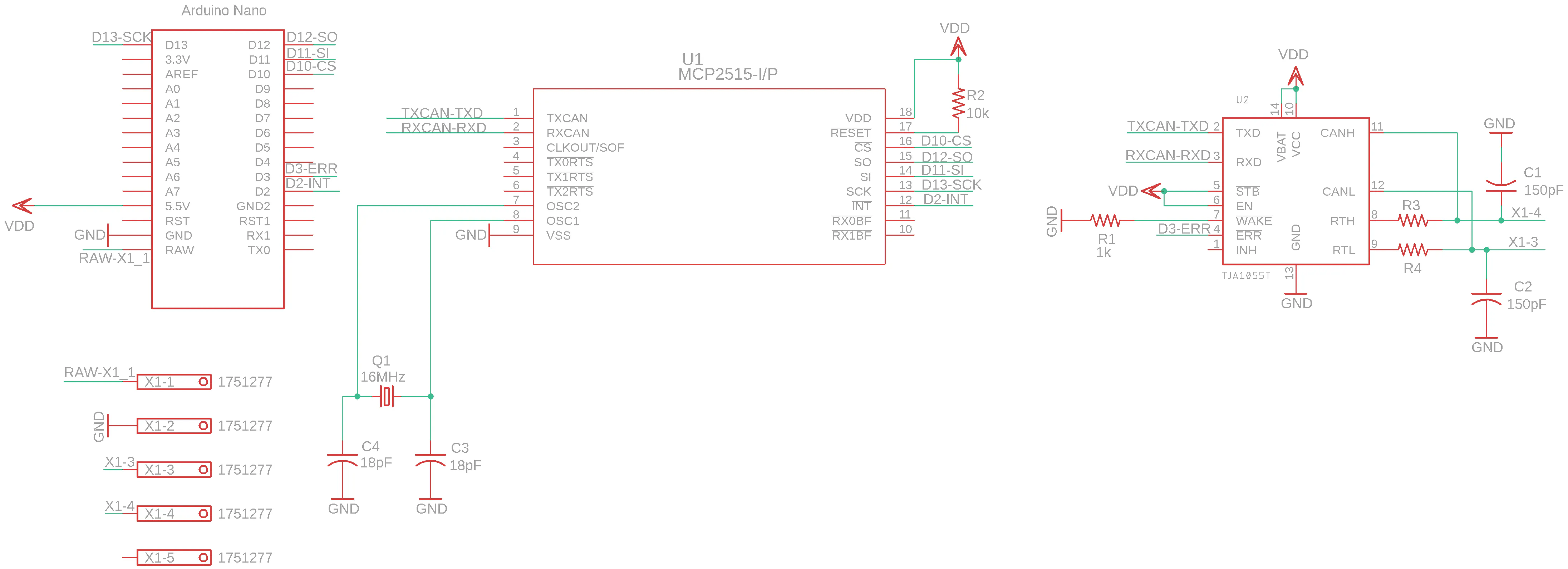
I decided to blueprint a circuit board for the Can-shield and integrate my Arduino Nano into it. Master components needed for the Tin can-shield were
- MCP2515 Stand-Alone CAN Controller with SPI Interface (Like shooting fish in a barrel to communicate with Arduino via SPI)
- TJA1055 Enhanced fault-tolerant CAN transceiver
- 16 MHz Crystal Oscillator
- resistors, capacitors and screw terminal block
- excursion board
TJA-1055T Application Hints [5] -document was useful when I dimensioned resistors and capacitors. I used Arduino CAN Tutorial [6] when I drew the connections between Arduino and MCP2515.
I designed the excursion board in Autodesk Eagle. I didn't pay too much attention to the circuit board blueprint specifics, because I knew that manufacturing and shipping of the board would take its own time. I ordered the printed circuit board from Itead.cc.
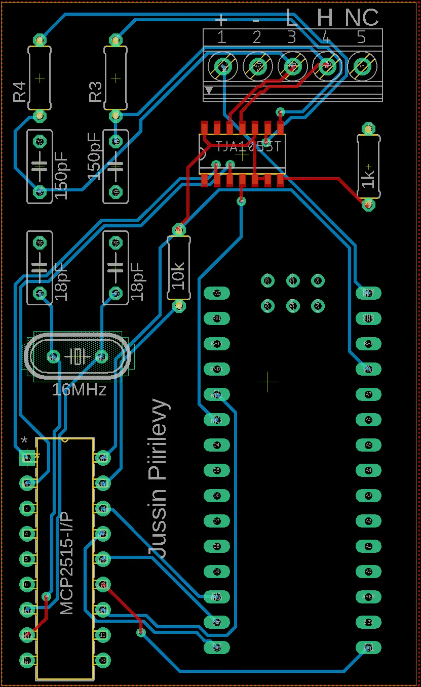
Circuit Board Design in Autodesk Hawkeye
Final Printed Circuit Board
Receiving and sending Tin-frames
I used this great MCP2515 library for Arduino, that allowed me to easily send and receive frames on the Tin jitney. Using the library was very straightforward, since information technology was so well implemented. In the following piece of code are examples of receiving and sending Can frames.
                              // Receive                                  struct can_frame canMsg;                                                  void loop() {

                                      if (mcp2515.readMessage(&canMsg) == MCP2515::ERROR_OK) {
                                      if(canMsg.can_id == 0x351){ // ID for speed information on Tin-Omnibus

                                      lv = canMsg.data[one];
                                      uv = canMsg.data[2]
                                      velocity = ((uv<<eight)+lv-i)/190;
                                      }
                                      }
                  }
                  // Send                                                                    struct can_frame canMsg2;
                  const uint8_t SPACE = 0x20;
                  const uint8_t KMH_MESSAGE [8] = {Infinite, SPACE, 0x4b, 0x4d, 0x2f, 0x48, Space, Space}; //ASCII for '  KM/H  '                                                  void setup() {                                                                      canMsg2.can_id  = 0x263; // Message ID for the 2d row of the DIS
                                      canMsg2.can_dlc = 8; // Length 8 bytes
                                      for(int j=0; j<8; j++){
                                      canMsg2.information[j] = KMH_MESSAGE[j];
                                      }                                                  void loop() {                                                                      mcp2515.sendMessage(&canMsg2);

                                      delay(twoscore); // The car radio sends it own radio station data every 0,8s to
                                      // the instrument cluster, so I have to send my information with much
                                      // higher rate, so the display won't offset to blink
                  }
CAN IDs
I found Audi Can bus message identifier list on Canhack.de [7] and I found the IDs for the start and second text line of the DIS. I also discovered the ID for vehicle speed information on txboard.de [viii].
Tested CAN IDs:
- 0x261 first DIS text line (length: eight bytes; form: ASCII)
- 0x263 2d DIS text line (length: viii bytes; grade: ASCII)
- 0x635 radio illumination (length: iii bytes; from left to correct: radio display backlight, radio buttons backlight, (?); (dimmest 0x0 - brightest 0x64)
CAN ID 0x351 (8 bytes from left to right) :
- 1. Ignition: 0x8 Ignition on
- 2. LV Vehicle speed lower value ("One time the engine is running and the automobile is stationary, changes the lower value to 1.")
- 3. UV Vehicle speed upper value
- four. Unknown
- 5. Unknown
- 6. Exterior temperature ane: (Decimal value)/2 - 40 Celsius
- 7. Outside temperature ii: (Decimal value)/ii - 40 Celsius (two different exterior temperature sensors?)
- 8. Unknown
Vehicle speed calculation:
speed in km/h = ((UV << 8 ) + LV - 1 ) / 200
Bulletin with ID 0x351 captured on the CAN bus: 8 0 0 0 0 60 60 0
During the capture, car had ignition on, and engine wasn't running. CAN frame suggests that ignition was on, temperature in my garage was eight degrees Celsius and vehicle speed was goose egg, which seems near right.
Timeline
- 1/nineteen/2021 : I haven't been able to test my speedometer in practice, because it's winter and I only drive the machine during summertime. Luckily, the hardest part is over and I have the concluding production in my hands. The balance of this project is just programming and testing the speedometer in do.
- 3/eight/2021 : The device is now installed under the dashboard and it's ready for testing and farther development.
Designing a casing for the device
Connecting the device to the wiring harness
The Device mounted under the dash side by side to the light switch
- 3/27/2021 : I took the car for a spin and after I did some modifications to the code, the speedometer started working properly.
Fully functioning Digital Speedometer
Sources
I used the following data from the previously mentioned GitHub-project [1] in my GALA Speedometer code:
- message length fixed 18-bytes
- terminal byte is checksum
- style to calculate the checksum
[1] GitHub: derpston/ Audi-radio-DIS-reader
[2] Volkspage: VW Cocky Study Programme 186
[3] Volkspage: VW Self Written report Program 238
[4] Volkspage: VW Self Study Programme 269
[v] TJA-1055T Application Hints
[vi] circuitdigest.com: Arduino Can Tutorial
[7] canhack.de: Audi RNS-E CAN Aufschlüsselung
[8] tx-board.de: ID 0x351
Author
Jussi Ristiniemi
Student at Tampere University, Finland
2nd year in Electric Engineering
Schematics
Code
Credits

Source: https://www.hackster.io/databus100/digital-speedometer-to-car-s-instrument-cluster-via-can-bus-66e273
Posted by: rossgother1977.blogspot.com
0 Response to "How To Install A Digital Speedometer In A Car"
Post a Comment